How to cut your refinery's cooling water requirements by 30-50%
Cut cooling water consumption by 30% - 50% in your refinery
Water is one of the key utilities necessary to process a crude oil into a refined product. One of the major users of water in a refinery is a cooling water system which removes excess heat from various heat sources including pump arounds, overhead condensers, and product streams going to tankages. The demand on cooling water systems is high and refineries will often find a constraint on their cooling water capacity, especially in the summer.
An average refinery in the United States gets 20% of the total water source from city or municipal water, which is the most expensive and limited source. This percentage jumps closer to 50% on the West Coast!
What are the benefits of reducing cooling water flow?
- Debottlenecks the process unit which is constrained with cooling water capacity.
- Increases reliability of operation, especially during the summer
- Significantly reduces Capex. Smaller pumps, piping, and structures, including a smaller cooling tower
- Significantly reduces Opex. Less water, pumping power, and chemical treatment
- Environmentally friendly by producing the same output with less water, chemicals, and electricity
- Supports UN sustainability goal No. 12: Ensure sustainable consumption and production patterns
What is the practical, economical, and doable way of achieving this?
It all starts with how we design our cooling water heat exchanger. Most of the time, process engineers follow traditional rule of thumb which is often based on centuries old shell and tube type heat exchanger technology. However, we are living in environmentally challenged times which requires critical transformations at the grass root level including heat exchanger design and technology use.
Let’s take an example of a big user of cooling water where condensation happens close to cooling water temperature: The Debutanizer Overhead Condenser.
Figure 1 (above)
The concept is to perform a temperature cross with cooling water.
In this example, Debutanizer column overhead vapors are cooled from 132°F to 100°F using cooling water at 85°F. Traditionally, cooling water outlet temperature is fixed less than or equal to hot fluid outlet temperature to avoid any temperature cross. In this case, cooling water outlet temperature was 100°F which will demand 2 million pounds per hour of cooling water flow to achieve the desired cooling duty. However, while the duty remains the same, the cooling water requirement can drop by 50% from 2 million pounds per hour to 1 million pounds per hour if we can achieve temperature cross with cooling water. In this case, the outlet temperature now is 115°F instead of 100°F. It’s a simple heat & mass balance.
Even though the concept looks simple, it’s not practical to achieve using a century old shell and tube heat exchanger technology. To achieve temperature cross as per figure 1, we would need four shell and tube in 2 series x 2 parallel configuration. These exchangers are usually erected on an elevated structure, making it uneconomical to implement. This is due to the huge impact on total installed cost driven by the large footprint and structural requirements necessary to accommodate four shell and tube heat exchangers. This is one good reason we don’t see many cooling water shell and tube exchangers designed with a temperature cross.
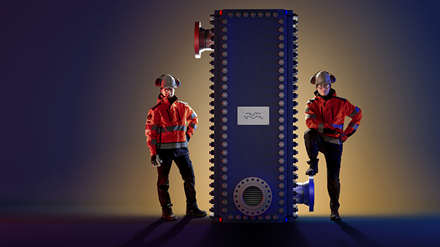
However, Compabloc© can achieve duty illustrated in Figure 1 in just one shell, due to its high heat transfer efficiency, multi-pass configuration on both the hot and cold sides, and close to full counter current flow arrangement. In this case, we would need only one Compabloc with 6.5 ft x 6.5 ft of footprint. This is extremely small compared to four shell and tubes, which leads to a lower total installed cost, an economically feasible project, and a reduction in the cooling water flow rate requirement to one million pounds per hour.
Figure 2 (above)
Today there are more than 500 Compablocs working as cooling water exchangers in crude oil refineries globally. Many of these are designed with temperature cross, saving millions of gallons of cooling water annually.
A recent example is from a refinery in the Midwest who decided to evaluate Compabloc in De-Isobutanizer overhead condenser service during an alkylation revamp project to increase capacity. Due to its small footprint of 3.5 ft x 3.5 ft, low total installed cost, and reduction in cooling water flow, they decided to install a Compabloc. Figure 3 demonstrates a steady high performance and low fouling over the course of 14 months of operation. Based on this performance, the refinery decided to install another Compabloc in Debutanizer overhead condenser service.
Figure 3 (above)
Ultimately, reducing the cooling water requirement in your refinery is the need of the hour for both resource optimization and operational flexibility of the process unit. One proven way to economically reduce the cooling water requirement is to design a cooling water exchanger with temperature cross with the help of Alfa Laval’s compact welded plate heat exchanger technology.
Find out more about Compabloc heat exchanger technology in refinery by Alfa Laval at https://www.alfalaval.us/refinery.
Why Compabloc?
There are more than 500 Compablocs installed around the world working as cooling water exchangers in crude oil refinery, saving millions of gallons of cooling water every year.

Read other relevant refinery blog posts
How to cut your refinery cooling water consumption by 30-50%
Reduce carbon intensity while improving bottom line in the refining sector
Overcome the challenges of cooling desalter water effluent
Debottleneck naphtha hydrotreaters with highest project ROI
Refinery alternatives to box coolers
Reducing energy consumption in industrial refrigerant systems
Benefits of Compabloc technology versus shell & tube
Using Packinox heat exchanger for catalytic reforming
Efficient wastewater cooling and reuse
Enabling sustainability goals of renewable fuels projects
Reducing scope emissions at refineries: A closer look into utilizing energy efficiency profitably
Energy efficiency opportunities around different heat exchanger positions in a fractionator – Part 1

